Description
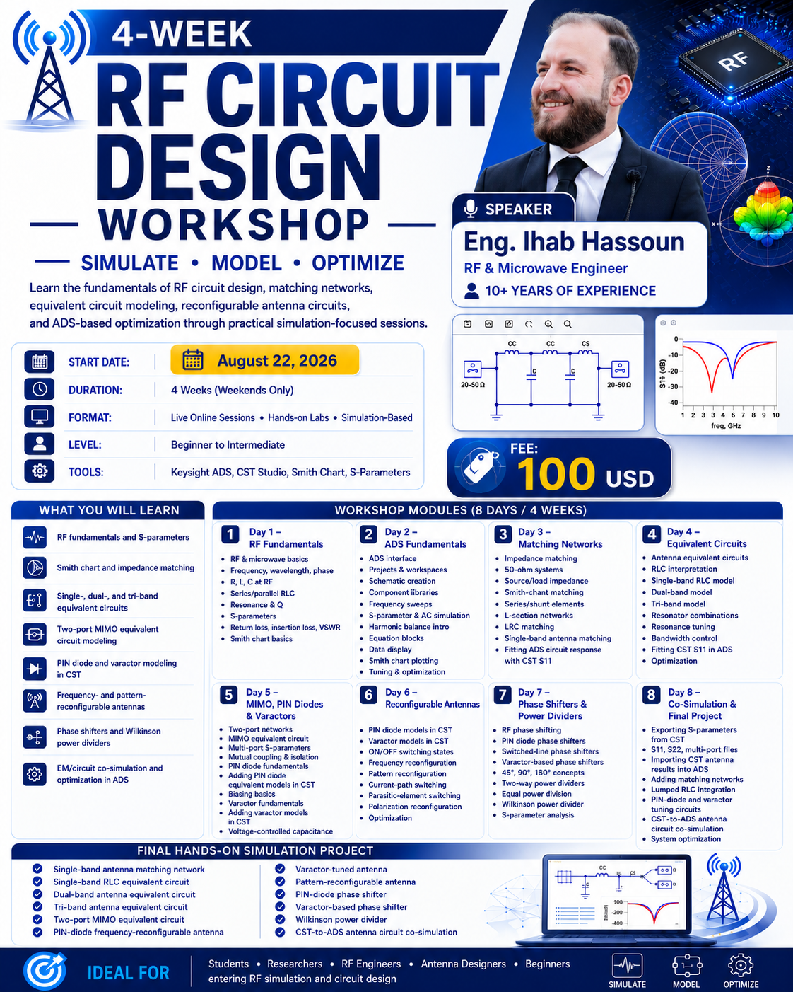
4-Week RF Circuit Design Workshop
Week 1 — RF Fundamentals and ADS Basics
Day 1 — Saturday: RF Circuit Fundamentals
- Introduction to RF and microwave circuits
- Frequency, wavelength, phase, and impedance
- Resistance, reactance, and complex impedance
- R, L, and C components at RF frequencies
- Series and parallel RLC circuits
- Resonance and quality factor
- Introduction to S-parameters
-
, , , and
- Return loss, insertion loss, isolation, and VSWR
- Smith chart fundamentals
- Basic impedance-matching concepts
Day 2 — Sunday: Keysight ADS Fundamentals
- ADS interface
- Creating projects and workspaces
- Schematic creation
- Component libraries
- Setting frequency sweeps
- S-parameter simulations
- AC simulations
- Introduction to harmonic balance
- Parameter sweeps
- Equation blocks
- Data display
- Smith chart plotting
- Tuning tool
- Optimization controller
- Basic RF circuit simulation examples
Week 2 — Matching Networks and Antenna Equivalent Circuits
Day 3 — Saturday: RF Matching Circuit Design
- Introduction to impedance matching
- 50- RF systems
- Source and load impedance
- Smith-chart-based impedance matching
- Series and shunt matching elements
- L-section matching networks
- RLC-based matching networks
- Single-band antenna matching circuit
- Selection of R, L, and C values
- Matching-network simulation in ADS
- Parameter tuning
- Matching-network optimization
- Comparing antenna response before and after matching
Day 4 — Sunday: Antenna Equivalent Circuit Modeling
- Introduction to antenna equivalent circuits
- Physical meaning of R, L, and C in antenna models
- Single-resonance RLC modeling
- Single-band antenna equivalent circuit
- Extracting approximate R, L, and C values
- Dual-band antenna equivalent circuit
- Two-resonator circuit models
- Tri-band antenna equivalent circuit
- Three-resonator circuit models
- Series and parallel resonator combinations
- Resonance-frequency tuning
- Bandwidth control using RLC parameters
- Fitting ADS circuit response with CST
- Equivalent-circuit optimization in ADS
Week 3 — MIMO, PIN Diodes, Varactors, and Reconfigurable Antennas
Day 5 — Saturday: MIMO Equivalent Circuits and Active RF Components
- Introduction to two-port networks
- Two-port MIMO antenna equivalent circuit
- Multi-port S-parameter concepts
- Mutual coupling between antenna ports
- Circuit representation of coupling
- Isolation in equivalent circuit models
- Coupled RLC resonators
- PIN diode fundamentals
- PIN diode ON-state equivalent circuit
- PIN diode OFF-state equivalent circuit
- Series resistance, inductance, and junction capacitance
- Basic PIN diode biasing concepts
- Varactor diode fundamentals
- Varactor equivalent circuit
- Voltage-dependent capacitance
- Using varactors for continuous frequency tuning
Day 6 — Sunday: Reconfigurable Antenna Simulation
- Adding PIN diode equivalent models in CST
- Adding varactor models in CST
- Modeling ON/OFF switching states
- Frequency-reconfigurable antenna simulation
- Frequency switching using PIN diodes
- Frequency tuning using varactors
- Pattern-reconfigurable antenna simulation
- Current-path switching
- Parasitic-element switching
- Ground/radiator switching concepts
- Introduction to polarization reconfiguration
- Simulation of multiple antenna states
- Comparison of S-parameters for different switching conditions
- Optimization of diode locations and lumped-element values
Week 4 — Phase Shifters, Power Dividers, and EM/Circuit Co-Simulation
Day 7 — Saturday: Phase Shifters and Power Dividers
- Introduction to RF phase shifting
- Phase response of RF circuits
- PIN diode phase shifters
- Switched-line phase shifters
- Varactor-based phase shifters
- Continuous phase tuning
-
, , and phase-shift concepts
- Phase-shifter simulation in ADS
- Phase-shifter optimization
- Introduction to RF power dividers
- Two-way power divider
- Equal power division
- Wilkinson power divider
- Isolation resistor
- Input and output matching
- Power-divider S-parameter analysis
- Wilkinson power-divider simulation and optimization in ADS
Day 8 — Sunday: EM/Circuit Co-Simulation and Final Simulation Project
- Exporting S-parameters from CST
- Introduction to Touchstone files
-
, , and multi-port files
- Importing CST antenna results into ADS
- Combining EM antenna models with RF circuits
- Adding matching networks to simulated antennas
- Adding lumped RLC components to antenna models
- Adding PIN diode circuits to simulated antenna results
- Adding varactor-based tuning circuits
- EM/circuit co-simulation
- Parameter tuning and optimization
- Comparison between CST and ADS responses
- Resonance-frequency comparison
- Bandwidth comparison
- Isolation comparison for MIMO antennas
- Optimization of complete antenna-circuit systems
Final Hands-On Simulation Project
Participants can complete one simulated design such as:
- Single-band antenna matching network
- Single-band RLC equivalent circuit
- Dual-band antenna equivalent circuit
- Tri-band antenna equivalent circuit
- Two-port MIMO equivalent circuit
- PIN-diode frequency-reconfigurable antenna
- Varactor-tuned antenna
- Pattern-reconfigurable antenna
- PIN-diode phase shifter
- Varactor-based phase shifter
- Wilkinson power divider
- CST-to-ADS antenna circuit co-simulation

Reviews
There are no reviews yet.